
Discover our latest resources
Filter posts:
-
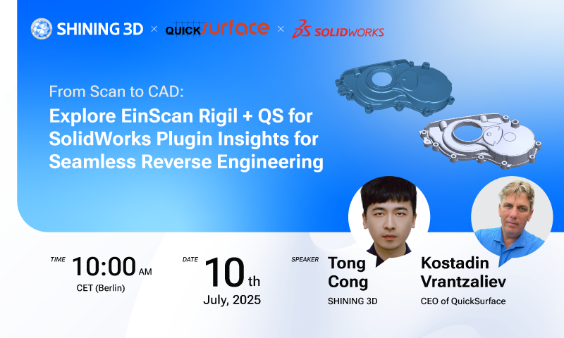
EinScan Rigil + QuickSurface for SolidWorks Plugin Insights for Seamless Reverse Engineering
Language: English
Rewatch -
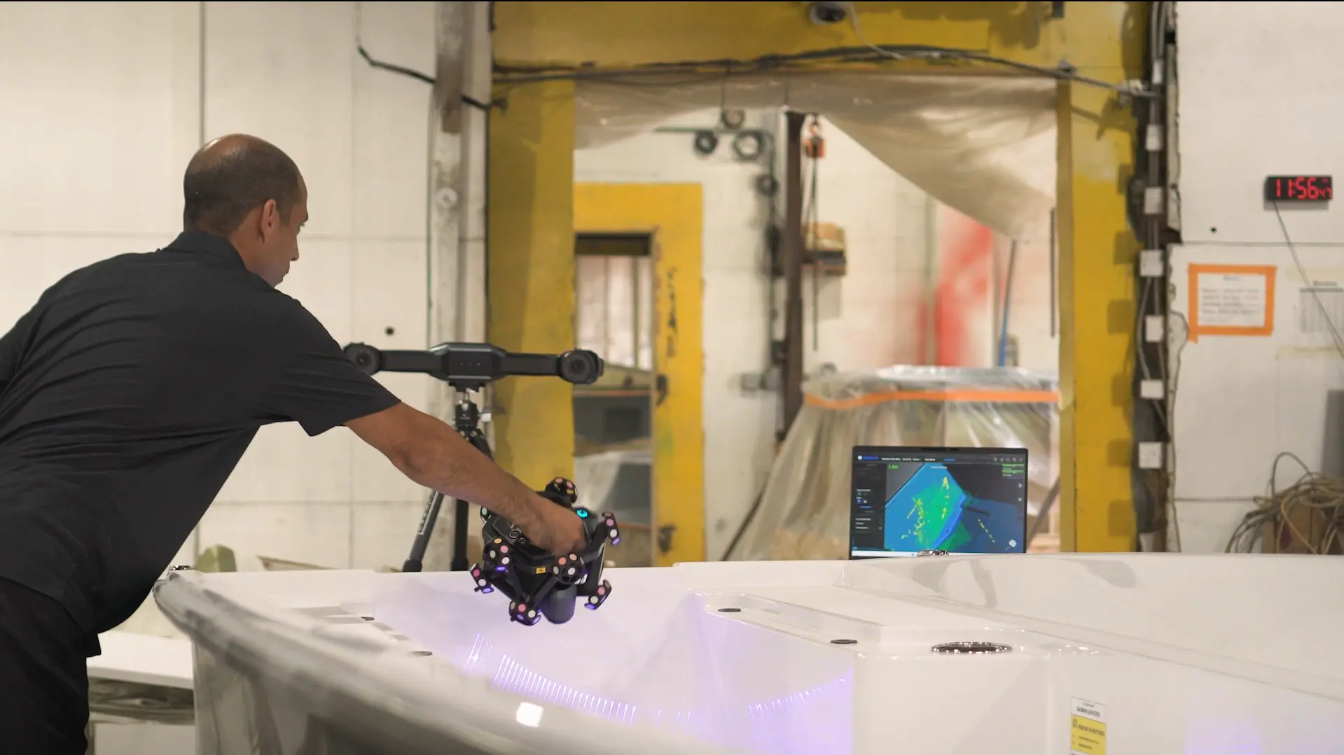
How High-Accuracy 3D Scanning Technology Advances Marine Mold Manufacturing and Inspection
Discover how SHINING 3D’s FreeScan Trak Nova enhances marine mold manufacturing and inspection, enabling accurate 3D scanning, reverse engineering, and CAD-based part validation for the boatbuilding industry.
Learn More -

Juliá Automobile x SHINING 3D: When Passion Meets 3D Scanning Technology, Classic Porsche Reborn
This article highlights how Spain Porsche restoration expert Juliá Automobile leveraged SHINING 3D's FreeScan Trak ProW to complete a high-accuracy reverse engineering project for a 1995 Porsche 993.
Learn More -
-
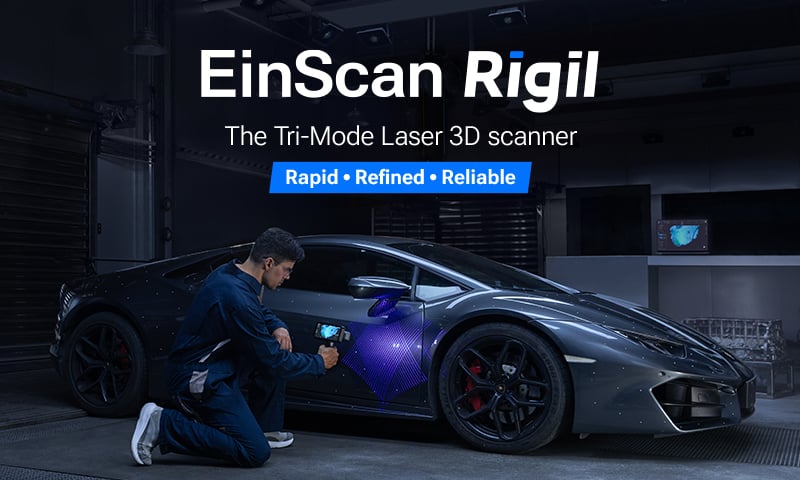
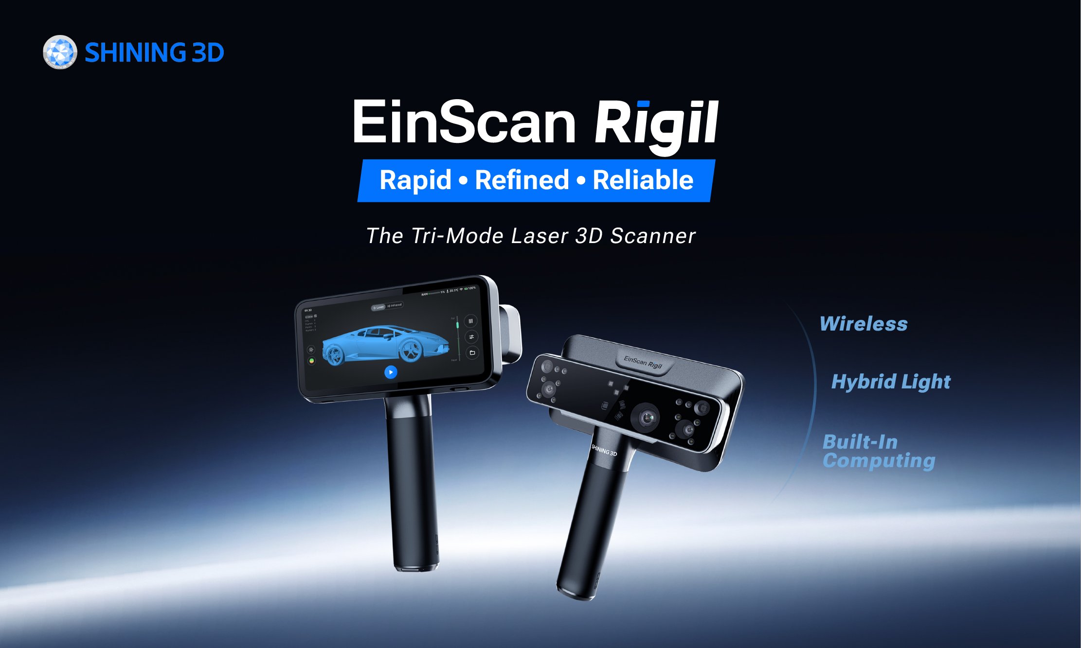
EinScan Rigil Launched: The World’s First Tri-Mode Laser 3D Scanner
SHINING 3D is proud to announce the launch of EinScan Rigil, our latest 3D scanner designed to deliver rapid, refined, and reliable scanning capabilities for a variety of applications.
Learn More -
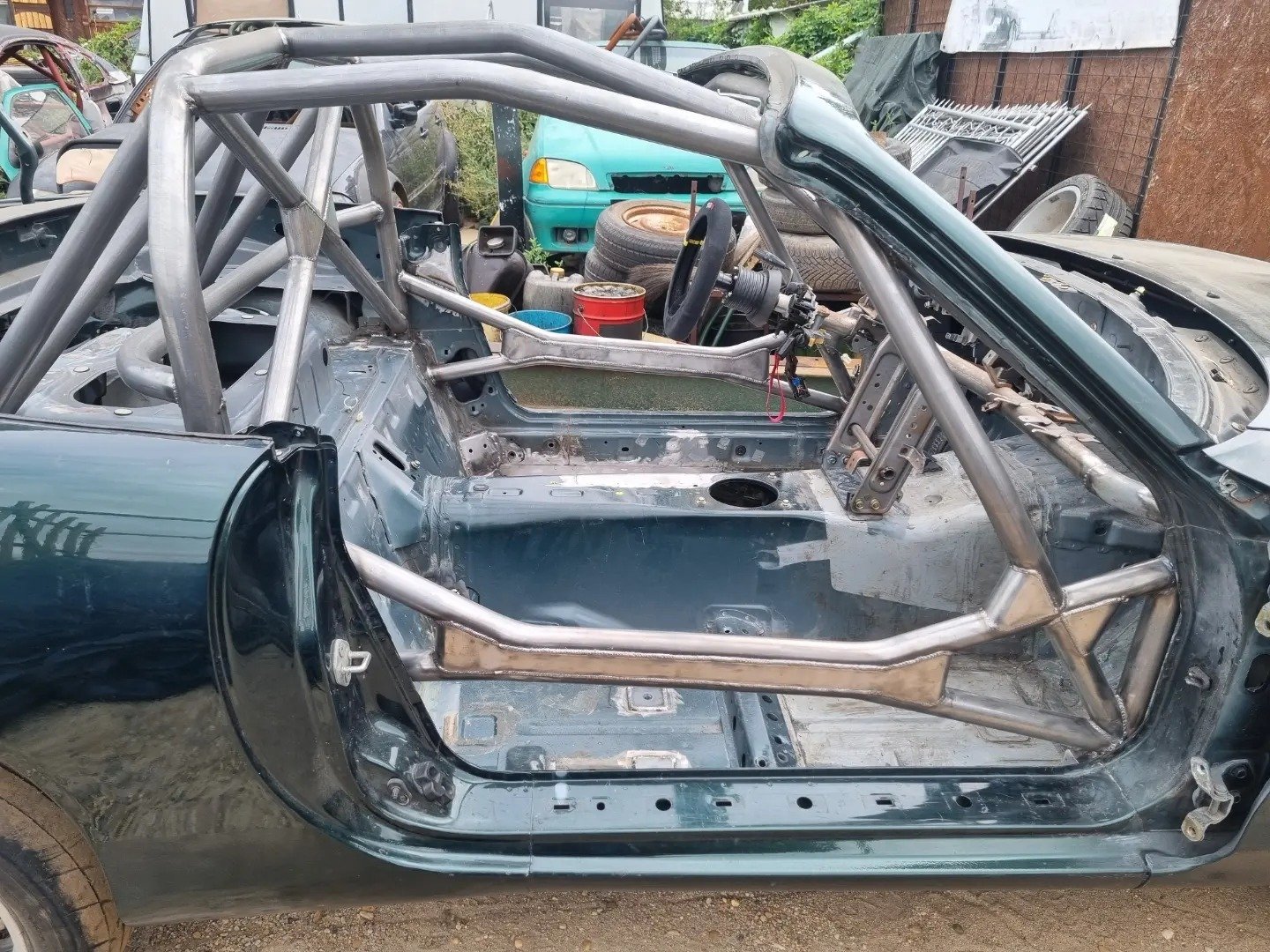
Application and Advantages of 3D Scanning in Roll Cage Design
Discover how Modception uses SHINING 3D’s FreeScan Combo Series to boost roll cage design with 3D scanning—improving accuracy, efficiency, and safety.
Learn More -
-2.webp)
How Babylon Engineering Turbocharged Auto Part Production with 3D Scanners
Once relying on traditional tools like vernier calipers and tape measures, Babylon Engineering has transformed its production workflow by adopting high-accuracy 3D scanning technology.
Learn More -
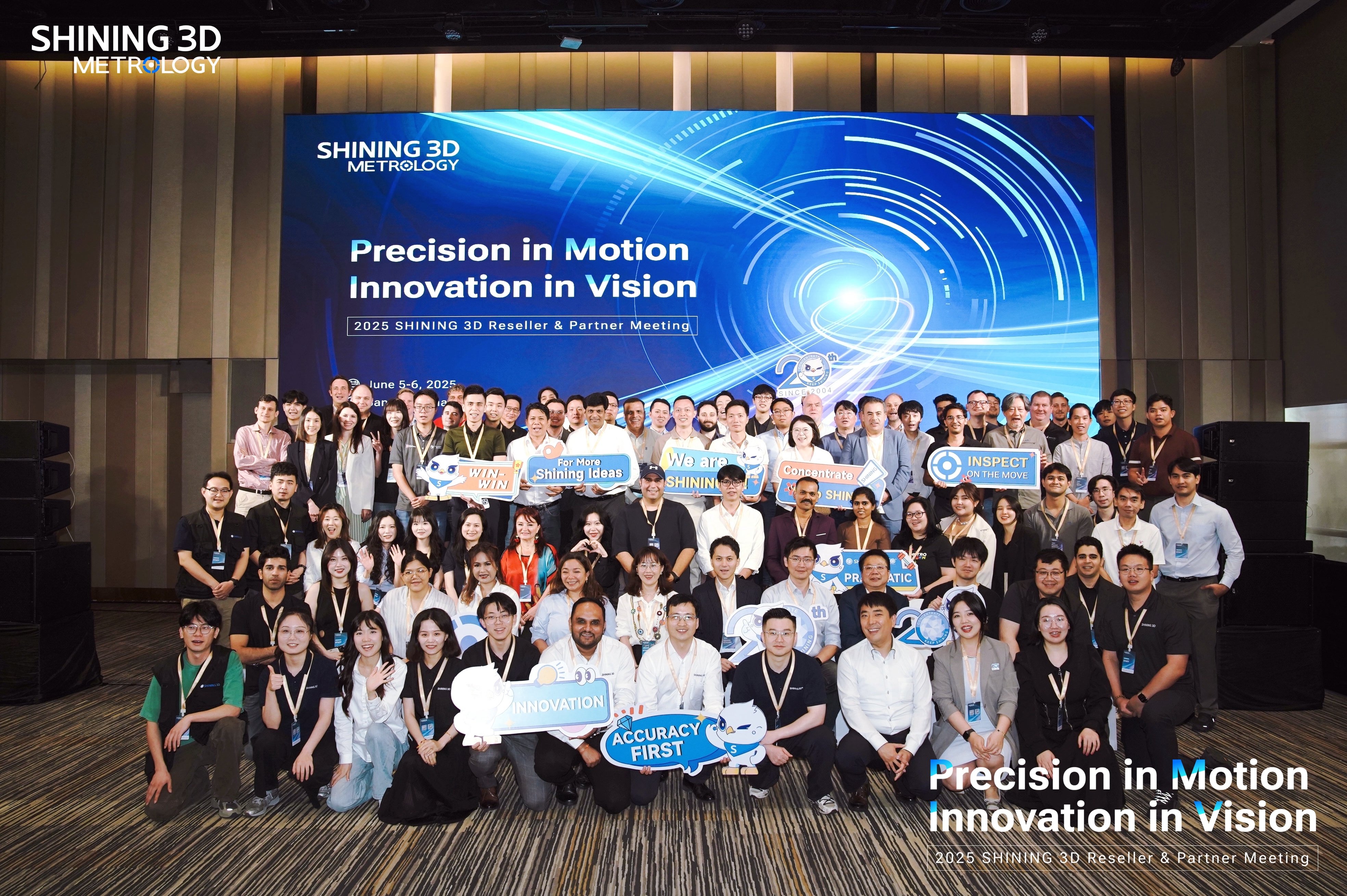
SHINING 3D Ignites Innovation at Global Reseller & Partner Meeting in Bangkok
SHINING 3D's Global Partner Meeting in Bangkok concludes, unveiling new 3D solutions, product innovations, and fostering future collaborations.
Learn More -

Reverse Engineering with 3D Scanning: Faster, Smarter, Easier
Learn how 3D scanning transforms CAD reverse engineering. Explore tools, workflows, and real-world 3D scan to CAD applications in design and manufacturing.
Learn More