


Guides/101
Published on Aug 18th 2026
Standardizing 3D Inspection Workflows in 2026
Standardized 3D inspection workflows reduce process variability by establishing consistent measurement protocols across production lines and facilities. Industrial metrology 3D scanners capture millions of data points in seconds, delivering full-field measurement that traditional contact methods cannot match.
Manufacturing quality depends not only on accurate measurement, but also on whether that measurement can be repeated consistently across operators, shifts, production lines, and facilities.
A standardized 3D inspection workflow establishes consistent procedures for defining measurement requirements, selecting equipment, scanning parts, evaluating results, and documenting findings. By reducing measurement variability, manufacturers can make quality decisions with greater confidence, detect dimensional problems earlier, and build a more reliable foundation for continuous improvement.
Industrial metrology 3D scanners further support this approach by capturing millions of surface data points quickly and providing full-field measurement for complex components.
Key Takeaways: Standardizing Dimensional Inspection Workflows
-
Standardized 3D inspection workflows reduce measurement variability by establishing consistent inspection procedures.
-
Industrial metrology 3D scanners provide full-field measurement and can capture complex surface geometry rapidly.
-
Standardization requires more than equipment: measurement requirements, scanning procedures, inspection templates, calibration, and operator training must also be controlled.
-
Inspection software helps standardize GD&T evaluation, reporting, and data analysis.
-
Automation can further reduce operator-dependent variation and support high-volume or 100% inspection.
-
Reliable inspection data enables manufacturers to reduce scrap and rework while supporting continuous improvement.
What Is 3D Inspection Workflow Standardization?
Dimensional inspection workflow standardization means establishing documented and repeatable procedures for measuring parts and components.
A standardized workflow defines:
-
What needs to be measured
-
Which tolerances and standards apply
-
Which measurement equipment should be used
-
How parts should be positioned and scanned
-
How inspection results should be evaluated
-
How results should be documented and reported
-
How equipment accuracy and operator competency are maintained
The objective is not simply to make every operator use the same equipment. The objective is to make inspection results comparable and traceable.
Without a standardized process, differences between operators, shifts, equipment, or facilities can introduce measurement variation. A dimensional deviation may then be difficult to classify as either a true manufacturing defect or an artifact of the inspection process.
Standardization establishes a consistent baseline so that changes in inspection results can be interpreted with greater confidence.
Why Does Inspection Variability Cost Manufacturers Money?
Inspection variability creates costs because manufacturers need reliable measurement data to make production decisions.
For example, different alignment methods can produce different dimensional results. If inspection procedures change between operators or shifts, a part may appear to pass under one method and fail under another.
This creates two risks:
-
False rejects: conforming parts may be classified as defective.
-
Defect escapes: actual defects may remain undetected.
Inconsistent inspection can also delay problem detection. A dimensional issue discovered early in machining is generally easier and less expensive to correct than one discovered after additional manufacturing or assembly operations.
A standardized inspection workflow therefore helps move quality control from reactive detection toward earlier process feedback.
How to Build a Standardized 3D Inspection Workflow
Step 1: Define Your Measurement Requirements
Start with the manufacturing requirements rather than the equipment. Determine:
- Which features are critical to product function
- Which tolerances apply
- Which industry or customer requirements must be followed
- Which GD&T characteristics need to be evaluated
- Which datum references should be used
Document these requirements before selecting equipment or developing inspection procedures. This documentation becomes the reference for the rest of the workflow and helps ensure that different operators inspect the same part according to the same criteria.
Step 2: Select Appropriate Metrology Equipment
Once measurement requirements are defined, select equipment based on the actual inspection application. Important considerations include:
- Part size
- Required accuracy
- Surface characteristics
- Geometry complexity
- Required measurement range
- Portability and shop-floor requirements
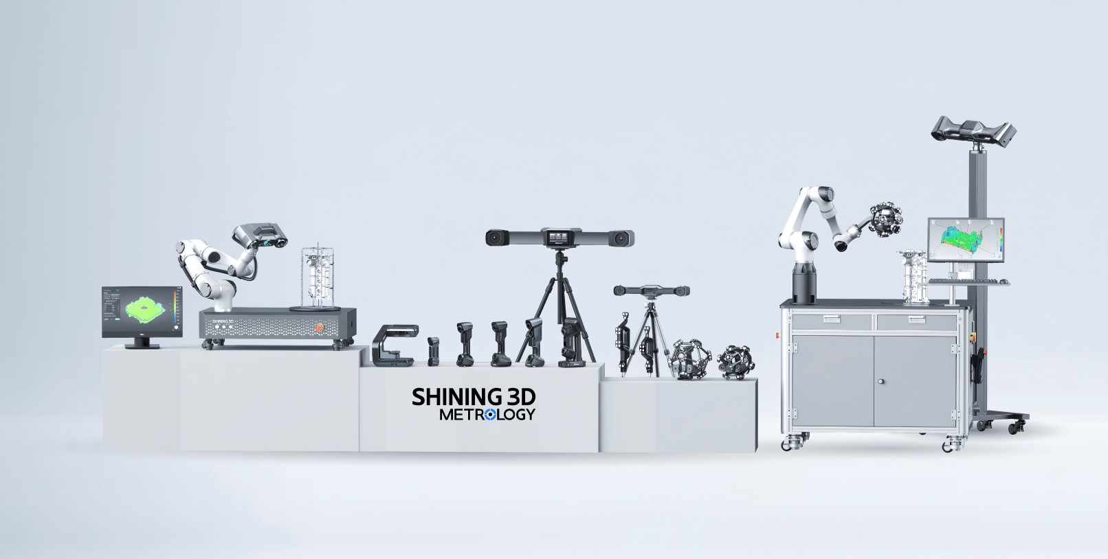
For example, for small precision components, high-resolution systems such as the OptimScan Q12/Q9 HD can provide high-accuracy measurement.
For larger components and portable inspection, solutions such as FreeScan Trak Nova and the FreeScan Combo Series provide greater flexibility.
For inspection directly on the shop floor, inspection-ready systems such as FreeScan Omni can support scan-to-inspect and scan-to-report workflows.
The key principle is to match the measurement technology to the inspection requirement rather than treating one measurement method as suitable for every application.
Step 3: Establish Scanning Procedures
Equipment alone does not create repeatable inspection results. Operators also need clearly documented scanning procedures. Define:
-
Scanner settings
-
Scan overlap
-
Surface preparation
-
Environmental requirements
-
Part positioning
-
Alignment methods
-
Datum selection
-
Registration requirements
Special procedures may also be required for dark, reflective, or transparent surfaces. The purpose is to remove unnecessary operator-dependent decisions from the inspection process. A standardized scanning procedure allows different operators to follow the same process and makes results easier to compare.
Step 4: Create Reusable Inspection Templates
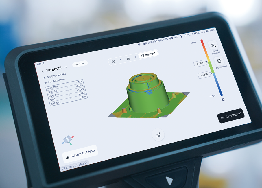
Build reusable inspection templates in your 3D inspection software. Reusable templates reduce decision-making variation between operators. These templates define which measurements to perform, which tolerances to apply, and how to present results. Every operator inspecting the same part type uses the same measurement definitions. Reports contain the same information in the same format.
SHINING3D Inspect supports standard-compliant GD&T evaluation with the ability to switch between ISO and ASME standards. This flexibility ensures your inspection data meets whatever requirements your customers or regulators specify.
Step 5: Implement Calibration Schedules
Measurement consistency depends on maintaining equipment accuracy over time.
Establish calibration procedures based on factors such as equipment usage and operating conditions. Record calibration results and maintain calibration history so that potential equipment-related trends can be identified.
SHINING 3D metrology systems undergo factory calibration in ISO/IEC 17025 accredited laboratories, while field calibration procedures help maintain measurement performance throughout the equipment lifecycle.
Calibration should therefore be treated as part of the standardized workflow rather than as a separate maintenance activity.
Step 6: Train and Qualify Operators
A standardized procedure is only effective when operators understand and follow it. Training should cover:
- Scanner operation
- Scanning techniques
- Part-specific measurement procedures
- Inspection software
- GD&T fundamentals
- Standardized workflow requirements
- Interpretation of inspection results
Operators should also understand why each procedure exists. This makes it easier to identify abnormal situations and provide useful feedback when the workflow needs improvement.
Document training requirements and track operator competency to maintain consistency across shifts and locations.


How Does Automation Further Improve Standardization?
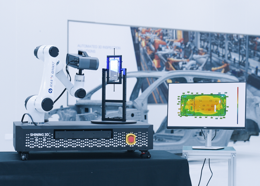
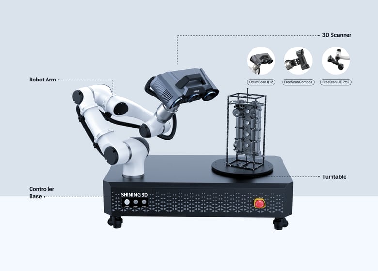
Automation takes standardization one step further by reducing human variability in repetitive inspection operations. Robotic systems position scanners and parts consistently, execute programmed scan paths repeatedly, and generate reports without operator intervention.
SHINING 3D automation solutions integrate 3D scanning with robotic handling for high-volume production environments. These systems maintain measurement consistency across thousands of parts while freeing skilled operators for tasks requiring human judgment.
Automation also enables 100% inspection where sampling previously applied. When inspection takes seconds rather than minutes, you can check every part rather than statistical samples. Defect escape rates drop accordingly.
How Does Standardized Inspection Reduce Scrap and Rework?
Standardization creates business value when reliable inspection data enables earlier and more accurate intervention.
Reduce Scrap Through Earlier Detection
First article inspection can identify tooling, fixture, or programming problems before they affect a larger production run. In-process inspection brings measurement closer to the manufacturing operation, allowing dimensional problems to be detected and corrected earlier. Inspection data can also support statistical process control (SPC). Trend analysis can reveal gradual process drift before dimensions move outside specification. The result is a shift from reacting to defective parts toward identifying process changes before they generate significant scrap.
Reduce Rework Through Better Deviation Information
Rework decisions become more precise when manufacturers can see the complete deviation pattern rather than relying on a limited number of measurement points. Full-field 3D inspection can show where deviations occur and quantify their magnitude. After rework, another scan can verify whether the intended correction was achieved. This reduces the risk of repeated rework caused by incomplete verification. 3D scanning can also support reverse engineering when legacy components do not have complete or usable CAD references.
How Do You Implement Standardization Across Multiple Facilities?
Standardization becomes more challenging when manufacturing takes place across multiple locations. The goal is not simply to create the same SOP at every site. Measurements produced at different facilities should also be comparable. A multi-facility approach should include:
-
Unified measurement system requirements: Facilities should use equipment with comparable measurement capabilities.
-
Common calibration procedures: Calibration methods and reference standards should be consistent and traceable.
-
Master inspection procedures: Centralized procedure development prevents every facility from creating its own interpretation of the workflow.
-
Inter-facility correlation: Identical reference parts can be inspected at different facilities to verify that measurement results agree.
-
Centralized inspection data: Cloud-based inspection data management can provide visibility across locations, helping quality teams identify local problems and share successful practices.
This approach turns workflow standardization from a local quality initiative into an enterprise-wide quality system.
In Conclusion: Taking the Next Steps Toward Standardized 3D Inspection
Standardizing a dimensional inspection workflow can help manufacturers reduce measurement variability, identify defects earlier, reduce scrap and rework, improve inspection efficiency, and establish more reliable quality data.
The most effective approach is to standardize the complete workflow—not just the measurement equipment.
Define measurement requirements, select appropriate metrology equipment, document scanning procedures, create reusable inspection templates, maintain calibration, and develop operator competency. Then use inspection software and automation to make those standards easier to execute consistently.
SHINING 3D metrology solutions provide the measurement and inspection foundation for this approach, combining metrology 3D scanners, inspection software, calibration, and automation capabilities.
With the right workflow, standardized inspection becomes more than a quality-control activity. It becomes a repeatable source of data that supports better manufacturing decisions and continuous improvement.
Share on Social Media


