


GUIDES/101
Updated on Aug. 31st 2026
3D Scanning Accuracy: What Affects Your Measurement Results?
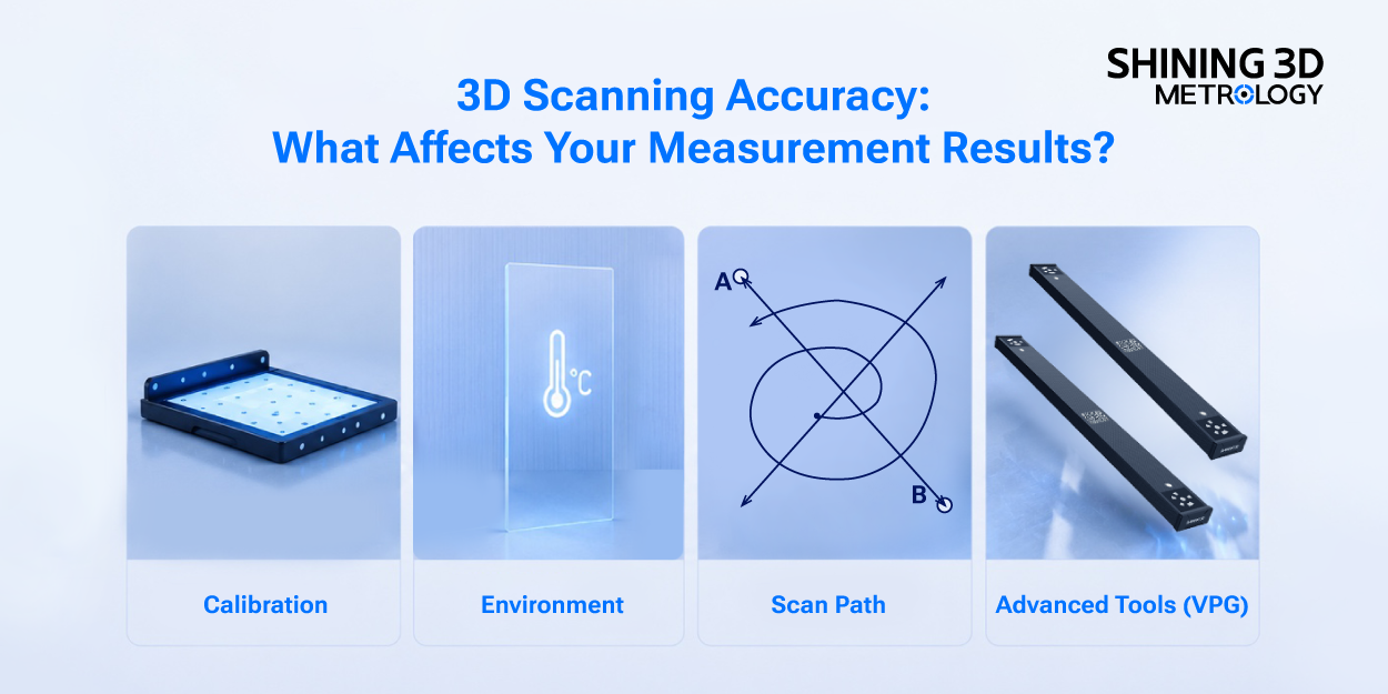
Learn the four key factors that affect 3D scanning accuracy, including calibration, environmental conditions, scan path optimization, and Video Photogrammetry (VPG) for large-scale measurement.
Two engineers can use the same metrology-grade 3D scanner on the same part—and still get different measurement results.
Why?
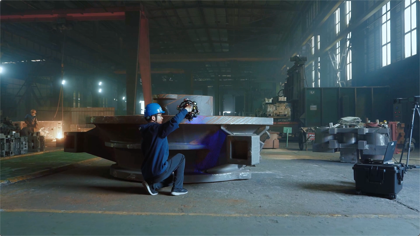
While scanner accuracy is defined by its hardware, the accuracy of a measurement is determined by the entire scanning workflow. From calibration and environmental conditions to scan path planning and global positioning, every step influences the quality of the final 3D data.
Understanding these factors is essential for achieving reliable inspection results and making full use of the metrology-grade 3D scanner.
Factor 1. Calibration
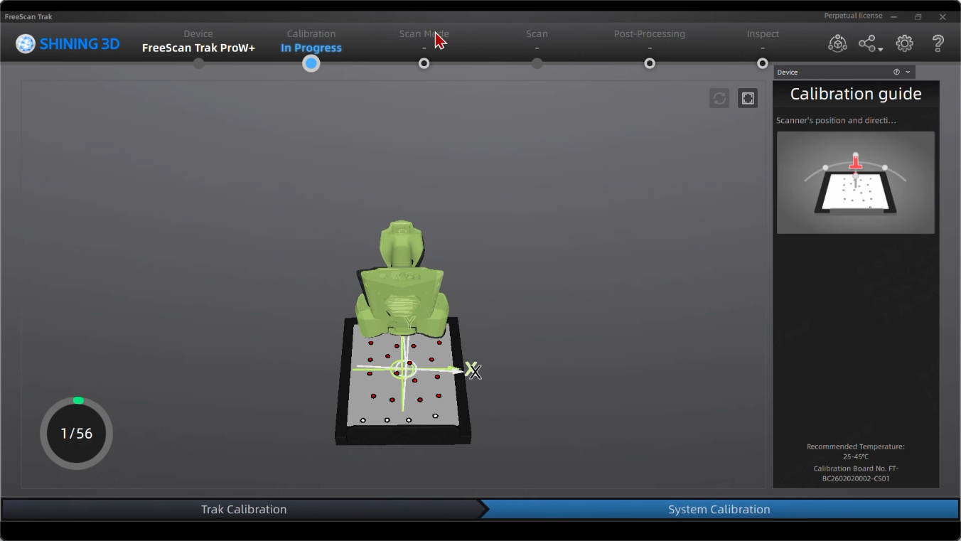
Calibration establishes the reference point for accurate measurement. Over time, transportation, daily operation, and temperature changes can cause micro-shifts inside the scanner's optical system. Although these changes may be imperceptible, they can affect measurement accuracy at the micron level.

Regular calibration restores traceability and ensures the scanner performs within its specified accuracy. For metrology applications, calibration should be performed according to the manufacturer's recommendations, particularly after transportation or significant environmental changes.
Factor 2. Environmental Conditions
Your surrounding environment dictates your data quality. Even the most advanced hardware will struggle if you ignore these invisible physical variables:
-
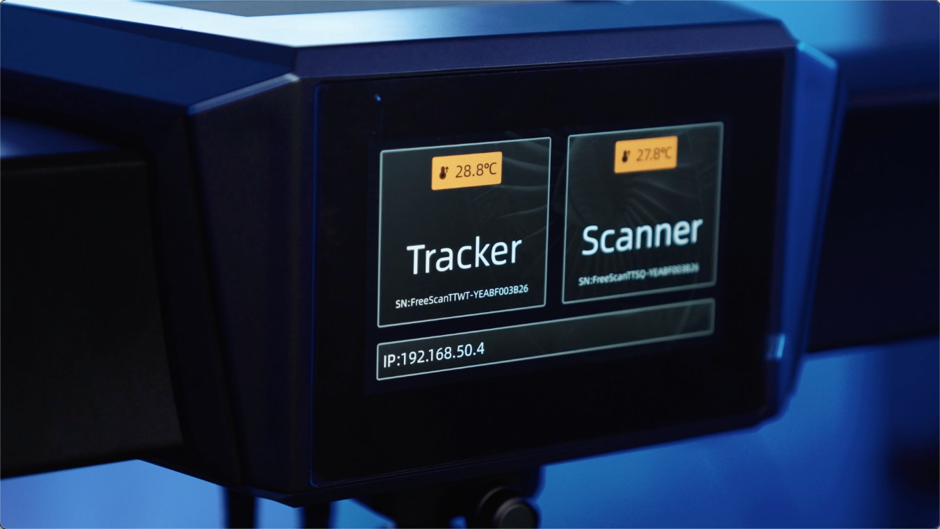
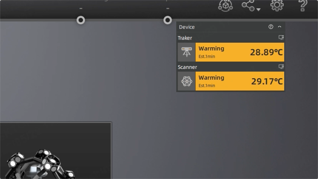
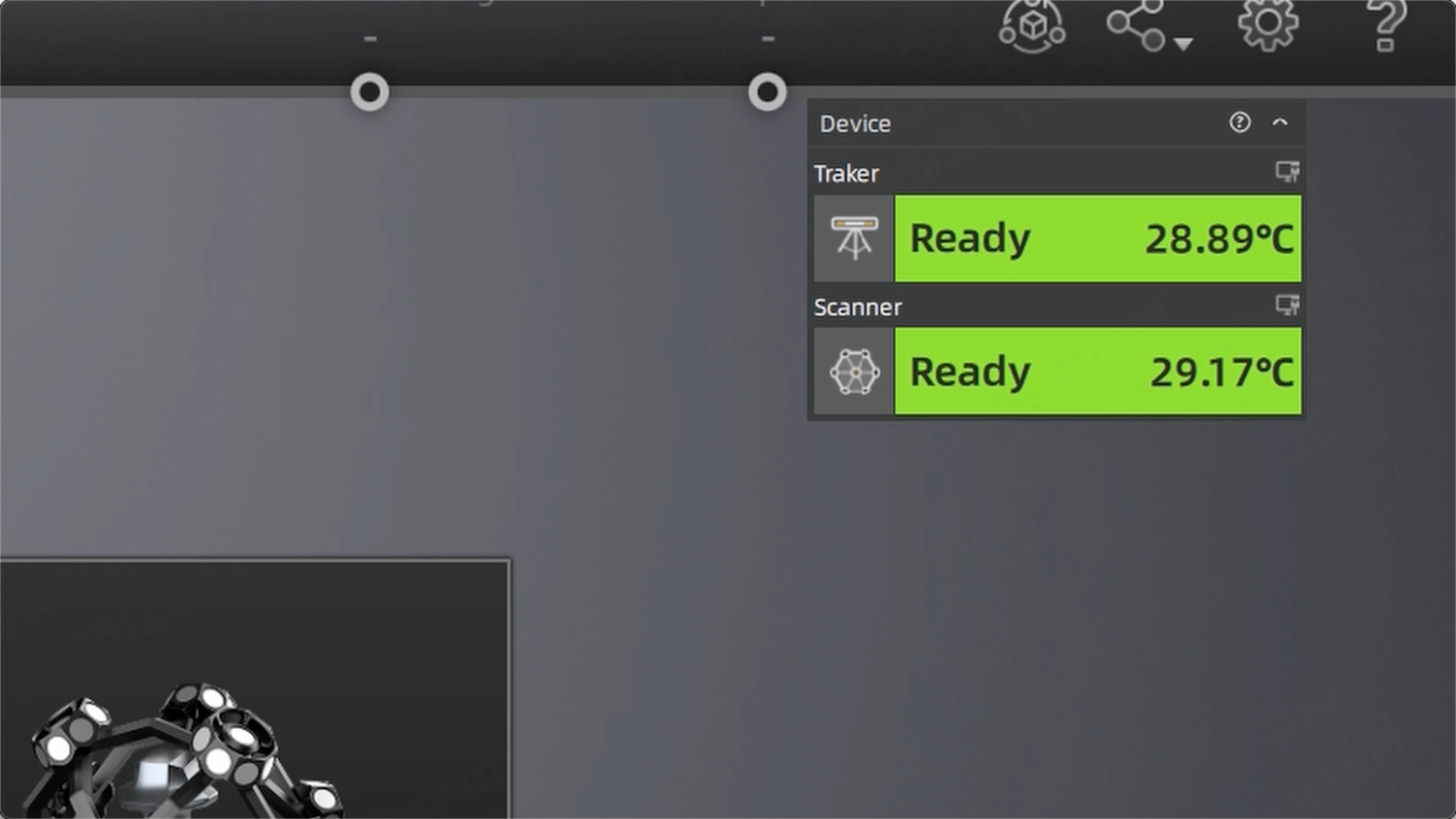
Temperature is one of the most important factors. It does not just warp your physical parts; they also affect the internal components of your scanner. Allowing the scanner to warm up and maintaining a stable ambient temperature help minimize thermal effects.
-
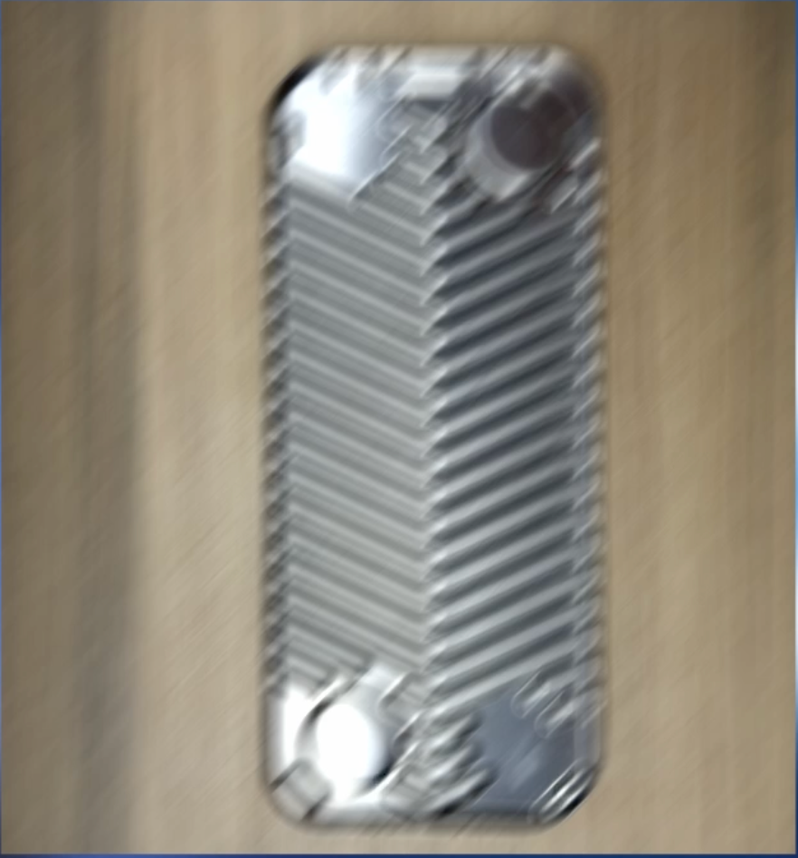
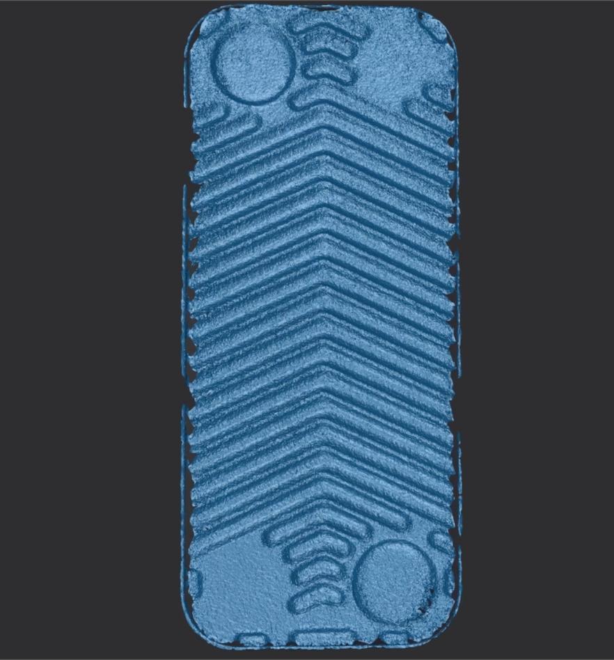
Vibration can also reduce data quality. Because 3D scanners functions as a highly advanced camera system, they capture thousands of images during scanning, vibration may blur raw 2D frames and result in a noise, poor-quality 3D mesh. Isolate your setup on a vibration-free workbench, or rely on reference markers for dynamic tracking.
Factor 3. Scan Path: Why the Way You Scan Matters
If your environment is controlled and the scanner is calibrated, your physical scanning habits might be introducing human errors.
During 3D scanning, the software continuously aligns thousands of individual frames to build a complete digital model. The alignment error between any two frames is microscopic. But as the scan goes on, these errors accumulate and grow—snowballing with every stitch. We call this Accumulated Error.
To better understand this effect, let's compare three common scanning strategies.
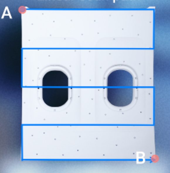
- Linear Scan Path
Scanning in straight, horizontal lines feels efficient, but on large, smooth surfaces, it creates the longest traveled distance from point A to point B with unconstrained start and end points. This method generates the highest accumulated error.
-
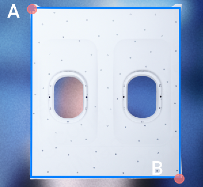
Closed Loop Scan Path
Scanning in loops brings the scanner back to its starting point. This constrains the path, the traveled distance from point A to point B is equal to the diagonal length of the part, which is drastically cutting the traveled distance and significantly reducing overall error.
-
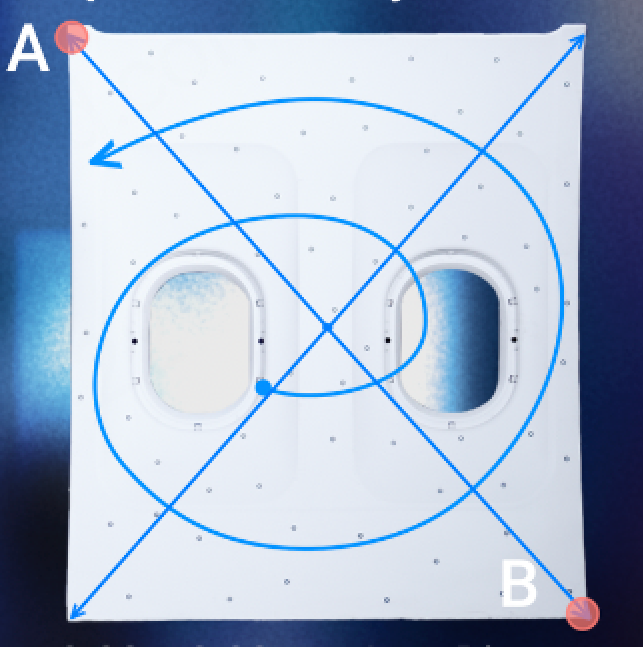
Spider-Web Style Scan Path
Start from a single center point and continuously expand outward in a circular. The expanding paths naturally overlap and constantly constrain one another. This interlocking effect pulls the overall data alignment inward. Because the paths are tightly cross-verifying each other as they grow, which drastically shrinks the accumulated error compared to drawing a large outer boundary from the beginning.
Comparison of Three Scan Paths
Assuming FreeScan Omni as operated scanner at its specified volumetric accuracy (0.02 + 0.03 mm/m), the theoretical accumulated error can be estimated based on the effective registration distance from Point A to Point B. The length and width of this scan sample are approximately 1.05 meters and 1.25 meters respectively.
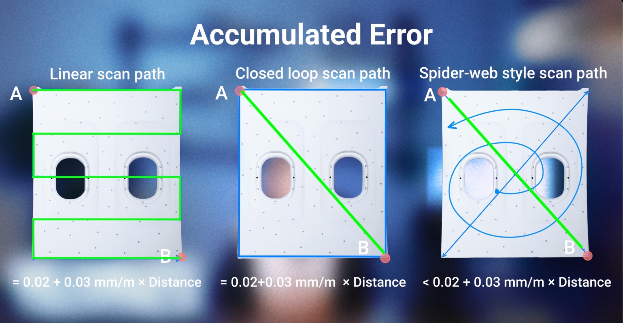
This relationship can be illustrated using the theoretical acummulated error calculation below.
|
Scan Path |
Linear Scan Path |
Closed Loop Scan Path |
Spider-Web Style Scan Path |
|
Distance from Point A to Point B |
5.25 m |
1.6 m |
< 1.6 m |
|
Accumulated Error |
0.1775 |
0.068 |
< 0.068 |
So for large or smooth surfaces, using closed-loop or spider-web style scan paths generally produces more consistent results than scanning in a single linear direction. Optimizing the scan path not only improves accuracy but also increases data stability throughout the measurement process.
Factor 4. Advanced Tool (VPG): Reduce Accumulated Error for Large-Scale Measurement
Even with an optimized scan path, accumulated error cannot be completely eliminated when measuring meter-scale parts. To reduce accumulated error, many large-scale metrology workflows incorporate photogrammetry before surface scanning begins.
By capturing coded targets distributed across the workpiece to establish a global coordinate framework. This provides absolute spatial references that help maintain dimensional accuracy across large objects while improving volumetric accuracy.
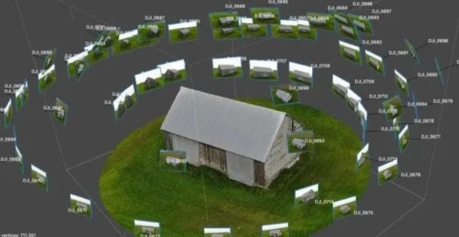
Photogrammetry Principle
.jpg "Video Photogrammetry Using Scale bar")
Video Photogrammetry Using Scale bar
Video Photogrammetry (VPG) further improves this workflow by using scale bars that continuously track these reference targets in real time. Rather than relying solely on sequential frame alignment, the scanner can repeatedly reference the global coordinate system, preventing alignment drift and maintaining consistent volumetric accuracy across the entire measurement volume.
|
|
Traditional Photogrammetry |
Video Photogrammetry |
|
Coded targets |
✅ |
❌ |
|
Setup time |
Longer |
Shorter |
|
Image acquisition |
Individual photos |
Continuous video |
|
Way to capture image |
Manual image capture |
Automatic frame extraction |
|
Acquisition time |
Longer |
Shorter |
|
Application |
Suitable for large-scale measurement |
Same application with improved efficiency |
|
Operator dependency |
Higher |
Lower |
Conclusion
A metrology-grade scanner provides the foundation for accurate measurement, but the final result depends on the entire measurement workflow.
Proper calibration ensures the scanner operates within its specified accuracy. A stable environment minimizes external disturbances. An optimized scan path reduces accumulated error by strengthening geometric constraints during frame registration. For large-scale inspection, technologies such as Video Photogrammetry (VPG) further improve volumetric accuracy by establishing a reliable global reference and minimizing alignment drift.
In other words, 3D scanning accuracy is not determined by a single specification—it is achieved through the combination of the right equipment, the right workflow, and the right scanning strategy. By understanding and controlling these factors, manufacturers can obtain more reliable measurement data, improve inspection repeatability, and make more confident quality decisions.
Looking to improve your 3D scanning workflow?
Explore our technical resources on metrology, volumetric accuracy, and Video Photogrammetry, or contact our experts to find the right solution for your inspection application.
Frequently Asked Questions
-
What affects the accuracy of a 3D scanner?
The accuracy of a 3D scanner depends on multiple factors, including scanner calibration, environmental conditions, scan path planning, surface characteristics, and accumulated error during data acquisition.
-
Why is calibration important for 3D scanning?
Calibration ensures that the scanner's cameras and optical components maintain their designed geometric relationship. Regular calibration compensates for small changes caused by transportation, vibration, or temperature fluctuations.
-
Does temperature affect 3D scanning accuracy?
Yes. Temperature changes can affect both the scanner and the workpiece. Maintaining a stable measurement environment helps reduce thermal errors and improves measurement consistency.
-
How can accumulated error be reduced during large-scale scanning?
Accumulated error can be minimized through proper scan planning, sufficient overlap between scan frames, and the use of photogrammetry for large parts.
-
What is volumetric accuracy?
Volumetric accuracy describes how accurately a measurement system maintains dimensional accuracy across a large measurement volume. Unlike single-point accuracy, volumetric accuracy reflects the cumulative influence of alignment errors over distance.
-
Why does accumulated error occur during 3D scanning?
Accumulated error occurs because every newly captured scan frame is aligned to the previous one. Although the registration error between adjacent frames is extremely small, these small deviations gradually build up over long scanning distances.
Share on Social Media


